

 Previous page
Most element partitioning studies between fluids and melts have employed bulk analytical techniques to determine the composition of the coexisting phases. A complementary approach is to trap the fluid phase as fluid inclusions within the quenched phase and then analyze directly the contents of the inclusions. Synthetic aqueous fluid inclusions in a glass matrix can be produced by rapidly quenching a fluid-saturated melt. We have investigated haplogranitic glass powders doped with 1000 ppm of elements ranging from Li to W in NaCl-solutions (up to 4 wt% NaCl). Reversal experiments with pure haplogranitic glass powders and doped NaCl-solutions (doped with up to 5 elements each at 1000 ppm level) have also been conducted. Syntheses were carried out in hydrothermal rapid-quench vessels at 2 kbars and 850°C.
The LA-ICP-MS technique permits the direct analysis of the glass matrix
and the contents of the fluid inclusions in the same sample. Analyses have
been carried out with the ICP-MS (ELAN 6000, Perkin-Elmer) in combination
with an excimer laser (ArF 193 nm) at the Institut für Isotopengeologie
und Mineralische Rohstoffe, ETH Zürich. These analyses yield time-resolved
spectra for each investigated isotope including the Ar carrier gas for
instrumental background determination, before the ablation process through
the glass matrix and into the inclusion (Fig. 3.8-8). When the ablation
process reaches the inclusion, a rapid
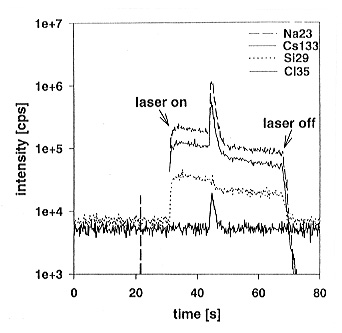 |
Fig. 3.8-8: Intensity versus time for the laser ablation of a fluid inclusion in doped haplogranitic glass. The laser drills through the glass matrix into the fluid inclusion. The opening of the fluid inclusion is indicated by rapidly rising intensities of Na, Cl, and Cs, which are dissolved in the fluid. Ablation of the matrix continues after the inclusion is completely ablated out. |
increase in signal intensity is observed. The ablation process is finished
when the inclusion is completely ablated out and the laser continues ablating
the glass matrix at the opposite end of the inclusion. The ablation of
liquids produces signals much stronger than that for solids. Thus, fluid
inclusion analysis requires separate calibrations for both the matrix and
fluid inclusion. We use a NIST SRM 610 glass for matrix calibrations and
external standard solutions (100 ppm element concentration) for the inclusion
calibrations. Cl serves as an internal fluid inclusion standard because
the bulk salinity can be determined independently by heating/cooling stage
fluid inclusion microthermometry. Due to the low sensitivity of the ICP-MS
to Cl, only analyses of fluid inclusions > 60 µm in diameter give
reproducible intensity signals for 35Cl. The size of the analyzed
inclusions range from 80 to 200 µm in diameter. For inclusions near
the sample surface (< 40 µm depth) we utilize a 40 µm diameter
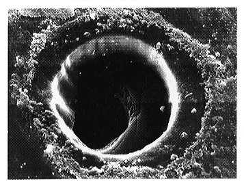
laser spot size. At greater depths, we preablate the glass matrix with
a larger beam (80 µm) before conducting the ablation process with
the smaller beam as the inclusion is approached (Fig. 3.8-9).
 |
|
|
Analyses of fluid inclusions in an undoped matrix (e.g. quartz) show inclusion signals clearly distinguishable from the matrix signal and require only the instrumental background correction. In contrast, evaluation of the inclusion signal in a doped matrix turns out to be more difficult due to the influence of the matrix. This effect cannot be related directly to the matrix signal before and after the inclusion. To evaluate these fluid inclusion signals we apply a correction of the matrix influence in addition to the instrumental background correction for each investigated isotope based on a highly compatible matrix element. Continued investigation of fluid inclusions in a doped matrix should improve the reliability of this technique compared to bulk methods.

Tel: +49-(0) 921 55 3700 / 3766, Fax: +49-(0) 921 55 3769, E-mail: bayerisches.geoinstitut(at)uni-bayreuth.de